Latest Technical Service
Remote Sensing Technology Service Examples

2008 The Iwate-Miyagi Nairiku Earthquake
-Surface Displacement from the M7.2 Earthquake-
Differential Interferometric SAR (DInSAR) Analysis
Latest Technical Services
Remote Sensing Technology Service Examples
2008 The Iwate-Miyagi Nairiku Earthquake
-Surface Displacement from the M7.2 Earthquake-
Differential Interferometric SAR (DInSAR) Analysis
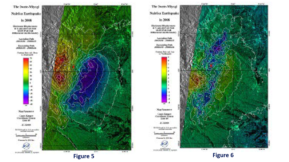
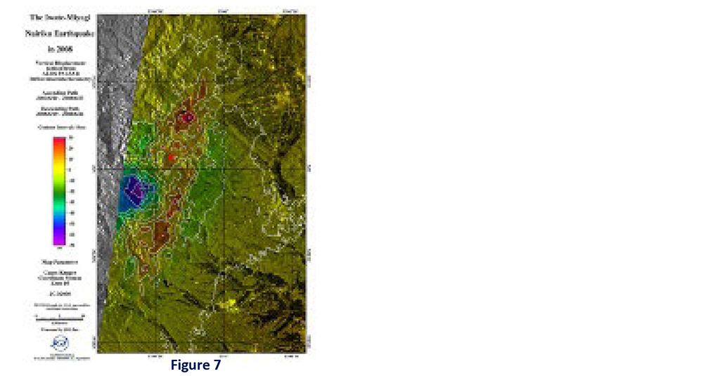
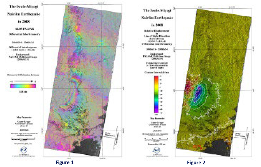
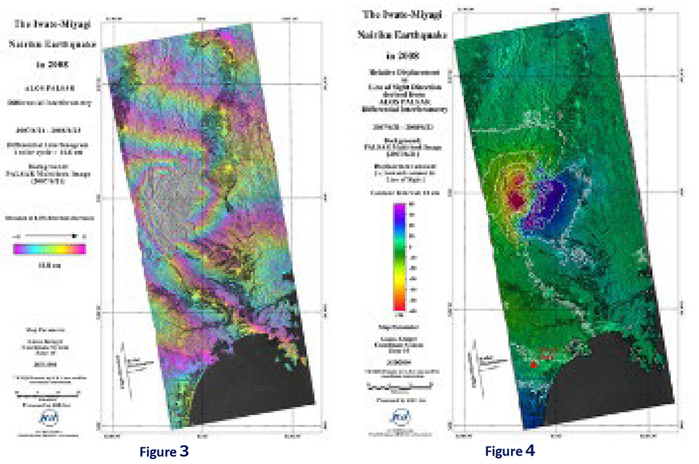
The figures below show the results of differential interferometric SAR processing (DInSAR) using ALOS PALSAR data acquired before (June 24, 2006, and June 21, 2007) and after (June 23 and June 24, 2008) “The Iwate?Miyagi Nairiku Earthquake in 2008” (Mw 7.2) in southwestern Iwate Prefecture. Both descending (Figures 1 and 2) and ascending (Figures 3 and 4) orbit data were analyzed to generate SAR differential interferograms and convert them into line-of-sight (LOS) displacement maps.
Figures 5, 6, and 7 show the results converted into 3D displacements based on the ascending and descending orbit interferograms. From these results, the following characteristics of surface displacement can be observed:
●Horizontal compression and vertical uplift/subsidence in the east-west direction is remarkable.
●Does the hanging wall moves east-southeast, whereas the footwall moves west-northwest?
●Uplift of the hanging wall and subsidence at the footwall. However, subsidence of up to 70cm is also observed in a part of the hanging wall of the fault. (It corresponds to the distribution area of Kurikoma volcanic ejecta.)
The LOS unit vectors for the ascending and descending orbit pairs are decomposed into (X, Y, Z) components as follows: ascending orbit (-0.5452, -0.0971, 0.8326) and descending orbit (0.6677, -0.1017, 0.7374), where X is positive eastward and Y is positive northward. The XYZ displacement components are obtained by multiplying these unit vectors by the LOS displacement values. Strictly speaking, the look angle varies across the cross-track direction, so these unit vector components also change slightly. For simplicity, the look angles near the epicenter were used in this calculation (ascending orbit: 33.63°, descending orbit: 42.49°).
Near the epicenter, coherence is low due to significant surface deformation caused by the earthquake, resulting in discontinuous interferometric phases (see figures above). Therefore, the actual displacements are likely larger than those calculated from the InSAR results.