Contribution to the Carbon Neutral Society
in 2050
Table of Contents
CCS/CCUS Related Fields
In Carbon dioxide (CO₂) Capture and Storage (CCS), CO₂ captured from emission sources is transported and injected in a supercritical state into porous subsurface formations called reservoirs at depths of more than 1000 meters. The reservoirs should be overlaid with impermeable rocks called caprocks, which prevent injected CO₂ from leaking upward over a long period of time. Before implementing CO₂ storage, it is necessary to find a package of a reservoir and caprock with sufficient CO₂ storage capacity using geophysical surveys. After implementing CO₂ storage, it is important to monitor the spatial and temporal behavior of injected CO₂ and to confirm that injected CO₂ stays in the reservoir as originally planned. Using three-dimensional (3D) subsurface visualization technologies that we have developed through many geophysical services, we strongly support CCS operators to find potential sites suitable for CO₂ storage and to monitor the CO₂ injected into the reservoirs.
In the survey for potential CO₂ storage site, reflection seismic data are first acquired and processed. The reservoir and caprock properties are evaluated by interpreting the processed data for geological structures and rock properties. Next, a reservoir model is created using the information previously obtained, and the behavior of the injected CO₂ is simulated to estimate the possible injection amount and to predict potential risks such as environmental impact and CO₂ leakage. We can provide a suite of evaluation and examination works as a one-stop service.
![[subsurface structure visualization and monitoring technology package in CCS-CCUS] etc...](https://jgi-inc.com/en/wp-content/themes/originaltheme/asset/img/business-field/carbon-neutral/3d_model.png)
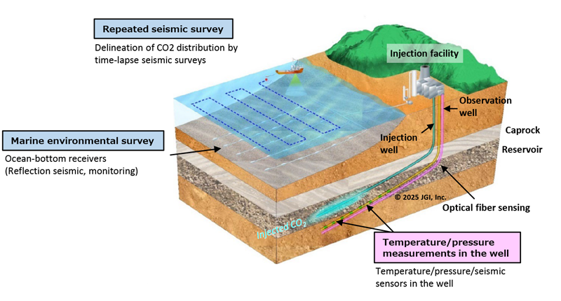
Our monitoring programs cover the entire lifecycle of CO₂ injection-before, during, and long after the injection process. We combine geophysical surveys, in-well measurements, satellite-based surface deformation monitoring, and environmental observation to provide a thorough evaluation of both storage performance and associated risks. Among these techniques, repeated geophysical surveys using elastic waves are especially valuable for tracking the spatial and temporal behavior of injected CO₂ within the subsurface. For each storage site, we design and implement an optimal integrated monitoring system, taking cost efficiency into account. Our services extend from system design and construction to operation and maintenance, all provided as a complete, turnkey solution.
Monitoring Specification Framework: Targets and Measurement Parameters
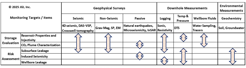
Source: Report of Tomakomai CCS Demonstration Project at 300 thousand tonnes cumulative injection (“Summary Report”)
https://jgi-inc.com/en/wp-content/uploads/2023/01/report202005_full.pdf
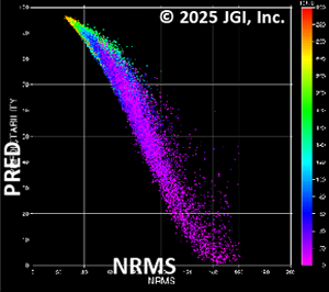
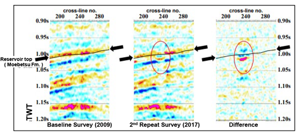
Evaluation of changes in time‑lapse seismic surveys using a reproducibility index
PRED: Predictability
An index that quantifies waveform similarity, excluding time shifts and polarity reversals between datasets.
NRMS: Normalized RMS
An index that normalizes sample-by-sample differences by amplitude and captures all discrepancies, including time shifts.
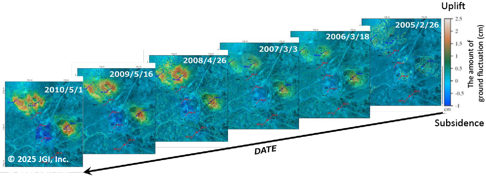
Estimated ground uplift and subsidence in In Salah CO₂ Storage Project, Algeria
Geothermal Resource Development
Imaging of geothermal reservoirs and fracture systems formed in deep subsurface structure is a key to the success of geothermal energy development. In order to more reliably capture fracture systems, we propose an integrated seismic survey that combines (1) DAS-VSP, (2) AE survey, and (3) Surface seismic survey.
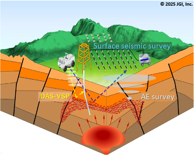
DAS:Distributed Acoustic Sensing
VSP:Vertical Seismic Profiling
DAS-VSP
DAS-VSP is a new seismic exploration method that uses DAS, which is one of distributed optical fiber sensing technologies, in VSP surveys conducted using surface seismic source and many observation points in Well. Since dense observation points can be set in Well, 3D reflection surveys and tomographic surveys can be carried out efficiently. Furthermore, we have developed and put into practical use a new analysis method for fracture systems using diffracted waves included in the data, and DAS-VSP is expected to be utilized as an innovative geothermal reservoir exploration method in the future.
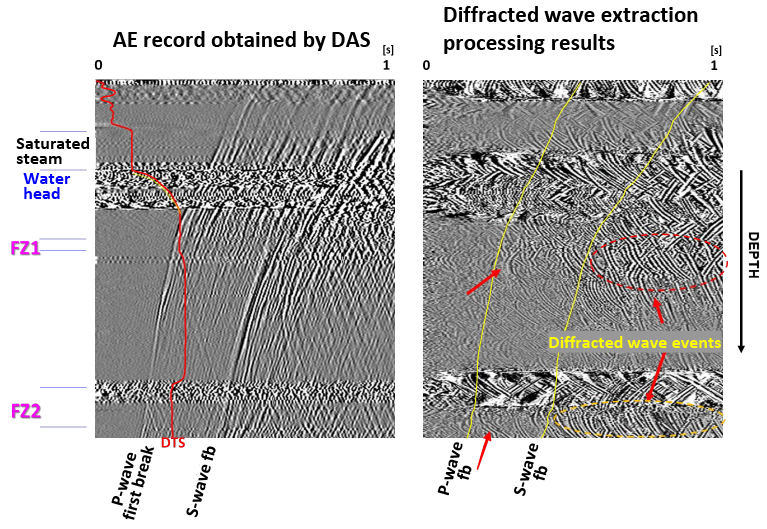
Examples of diffracted wave extraction and enhancement from AE records. (Left) DAS recording of Acoustic Emission (AE) generated near the Well. (Right) Recording after plane wave suppression and diffracted wave enhancement processing.
Learn more
AE survey
Advancing the understanding of fracture distribution can be achieved by analyzing AE hypocenter distributions generated by earthquake swarms in geothermal areas, as well as by changes in subsurface pressure conditions associated with well operations. To this end, we propose the deployment of dense, temporary surface observations using compact seismic survey equipment, supplementing the existing observation network. Such a dense observation system is expected to enable more precise estimation of AE hypocenter distributions and more accurate focal mechanism analyses, both of which are essential for characterizing fracture behavior.
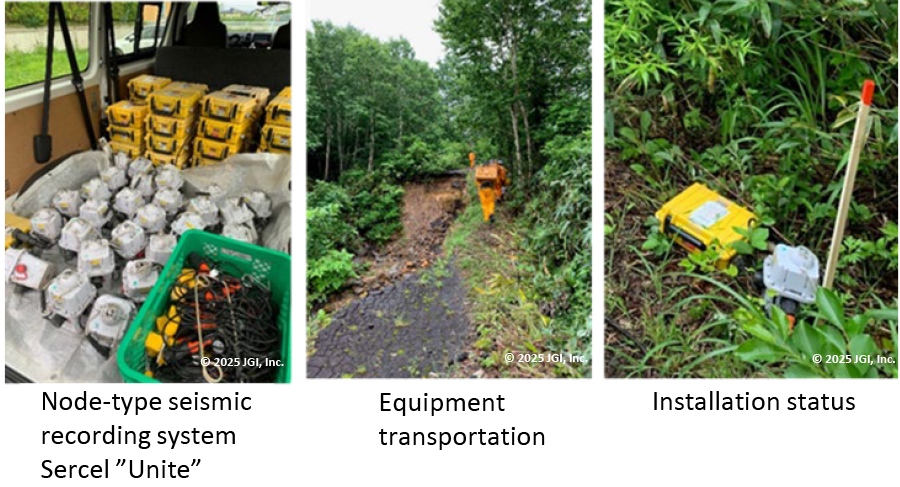
Surface seismic survey
Surface seismic surveys in mountainous geothermal areas must contend with severe surface conditions. However, when survey lines can be established along forest roads or mountain trails, fracture system characterization can be significantly advanced through 3D tomographic analysis and attribute analysis for fracture system evaluation using quasi-3D reflection data.
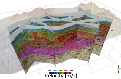
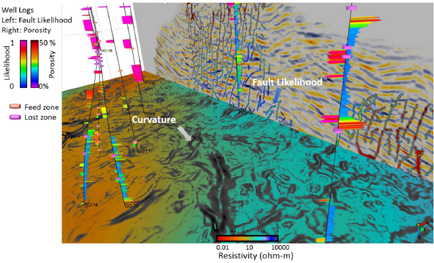
Figure 1:Examples of 3D tomography analysis in geothermal areas
The velocity distribution derived from tomographic analysis is superimposed on the reflection section for visualization. The analysis reveals medium- to long-term structural variations, characterized by high-velocity anomalies in geothermal zones and low-velocity anomalies in the present hydrothermal vent area.
Figure 2:Comparison of fracture evaluation attribute and resistivity record
By applying fracture system evaluation attribute analyses such as Curvature and Fault Likelihood to the 3D reflection records, the development of fractures can be visualized. This figure compares these attribute records with porosity logs estimated from resistivity well log analysis and with resistivity distribution maps from previous MT surveys (NEDO, 1985).
Offshore Wind Farm Development
Offshore wind power is attracting attention as an effective renewable energy source due to its potential. In the design of pile foundations for offshore wind turbines, it is necessary to employ technologies that can properly understand and evaluate the geological risks of the submarine ground. In particular, it is crucial to identify risks such as faults, soft sediments, and shallow gas, and to accurately visualize geological distributions in relation to bearing layers and engineering bedrock.
JGI offers comprehensive, end-to-end geological and geophysical survey services-from literature review to subsurface modeling and risk assessment-with a specialization in high-resolution 2D and 3D geophysical surveys. Through these services, we contribute to the advancement of the offshore wind power industry.
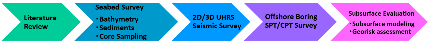
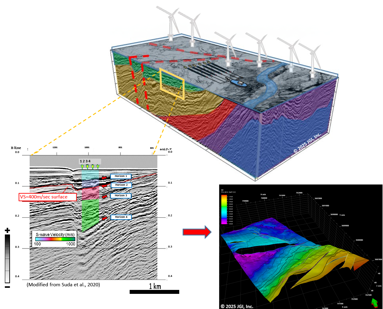
We can obtain deep subsurface P-wave and S-wave velocities, as well as the distribution of the engineering foundation surface (Vs400 m/s layer), by deploying seabed seismometers alongside high-resolution 2D and 3D seismic surveys.