Latest Technical Service

Integrated Geological Analysis Service
Latest Technical Services
Integrated Geological Analysis Service
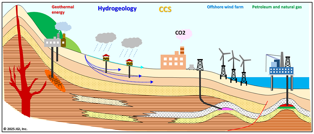
With decades of experience in oil and gas exploration, we have developed advanced expertise in data analysis, evaluation, modeling, and simulation techniques for geology, geochemistry, and geophysical surveys. These technologies are broadly applicable to various fields, such as oil and gas exploration, CCS, renewable energy development (such as geothermal and offshore wind power), and groundwater utilization and management.
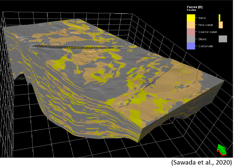
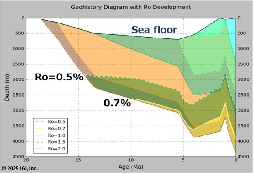
▶3D Geological Modeling, Petroleum System Modeling, and Fluid Flow Simulation
▶Flow-Mechanical Coupling Analysis
Understanding the flow behavior of CO₂ is indispensable for CO₂ geological storage. Furthermore, since concealed faults underground includes risks of CO₂ leakage and induced earthquakes, it is considered extremely important to evaluate their distribution and stability. In recent years, for monitoring methods to understand the flow behavior of CO₂, inverse analysis of surface displacement using InSAR is expected as one of the economical and effective monitoring methods. We offer a flow-mechanical coupling analysis service using TOUGH-FLAC (Rutqvist and Tsang, 2002) as an inverse analysis approach to estimate reservoir pressure based on surface displacement data. Flow-mechanical coupling analysis utilizing 3D geological models is considered to lead to more realistic and reliable fault stability evaluations because it uses a numerical analysis model capable of analyzing not only changes in pore pressure due to CO₂ injection but also local stress field disturbances.
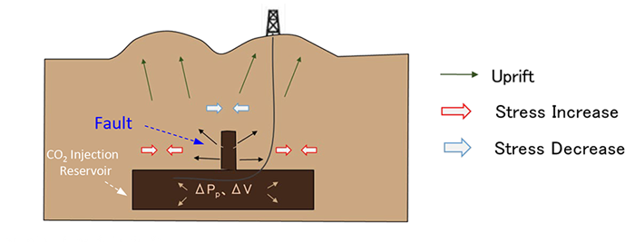
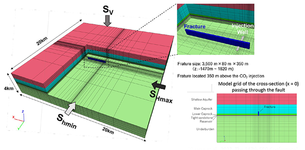
The fault connects from the reservoir where CO₂ is injected to the overlying caprock but does not penetrate the aquifer above the caprock.
(Ozawa et al., 2022, The 147th SEG Conference)
The double lobe on the surface is thought to be caused by lateral displacement due to expansion (dilation) accompanied by fault slip.
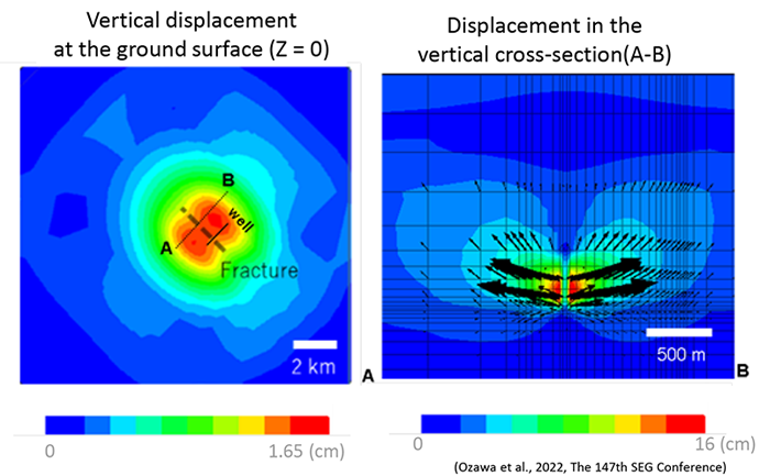
Model results show that CO₂ injection induces fault deformation, generating a double-lobed displacement pattern
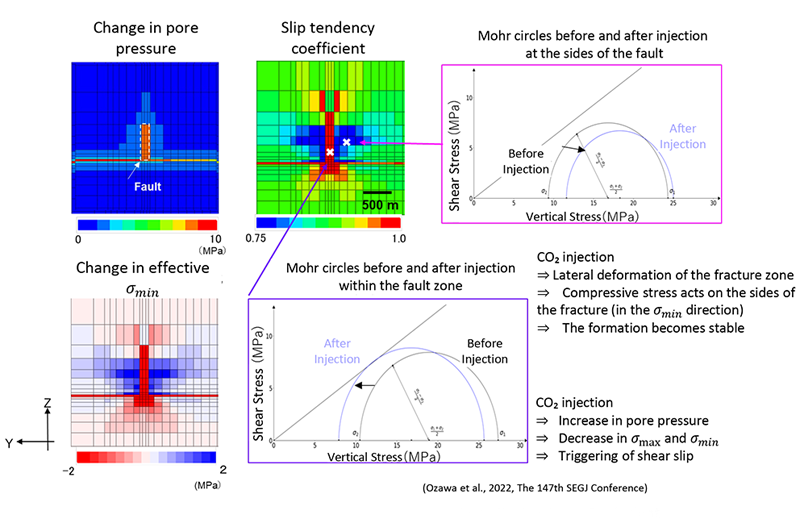
Within the fault zone, CO₂ injection increases pore pressure and reduces effective normal stress, shifting the Mohr circle to the left. The slip-tendency approaches 1, indicating the onset of shear slip. In contrast, along the sides of the fault, lateral deformation imposes compressive stresses, shifting the Mohr circle to the right and lowering the slip tendency; therefore, the formation is considered stable.