Non-Explosive Seismic Source
The explosive seismic source (e.g., dynamite) was commonly used in seismic surveys conducted in Japan. It is an impulsive-type source and generates a significant amount of energy capable of penetrating deep into the ground. However, since the mid-1970’s, in Japan, the explosive seismic source have been replaced, particularly in urban areas, by non-explosive sources, such as seismic vibrators. Since the use of explosives generate very strong vibrations and noise, also require drilling holes for loading explosives, various restrictions related to permits and approvals have arisen. As a result, considering safety and environmental concerns, seismic vibrators began to be used as the primary seismic source. As non-explosive seismic sources, seismic vibrators, hydraulic impactors, and weight-drop type sources are commonly used for land seismic surveys, whereas air guns, water guns, boomers, and sparkers are typically employed for marine seismic surveys.
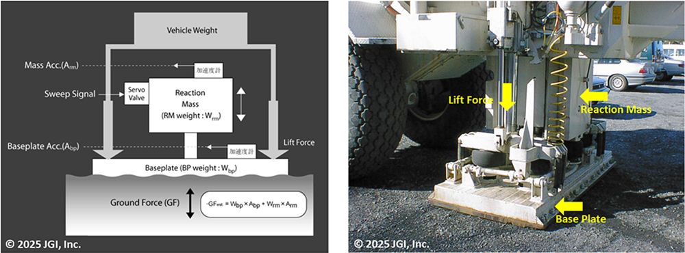
▶Vibrator seismic source (onshore seismic source)
Early vibroseis systems, as developed by CONOCO in the early 1950s, utilized a pair of counter-rotating eccentric masses. By rotating these weights in opposite directions at the same angular velocity, the system generated a vertical oscillatory force. This force was transmitted to the ground through a baseplate, producing a controlled vertical vibration ideal for seismic signal generation. This mechanical approach allowed for a relatively simple means of generating seismic vibration, but it had limited flexibility in controlling the vibration characteristics such as amplitude modulation, frequency sweep shaping, and precise timing synchronization. As vibroseis technology advanced, the mechanical vibratory systems were gradually replaced by hydraulic actuator-based designs in the early 1960s. The systems employ a hydraulic piston controlled by servovalves, which allow for precise and responsive control of the actuator’s motion. The servovalves regulate the flow of hydraulic fluid into the piston chambers based on real-time control signals, enabling precise controls that was not possible with earlier eccentric mass systems. The servo-hydraulic vibrator has been widely recognized for its effectiveness and has become the standard technology for land seismic surveys since the mid-1970s. In Japan, Japan Petroleum Exploration Co., Ltd. (JAPEX) introduced the Y-900 seismic vibrator manufactured by IVI in the United States in 1974. Since the late 1980s, JGI, a subsidiary of JAPEX, has successively introduced the seismic vibrators, such as the HEMI(large vibrator), the EnviroVIB(medium-sized vibrator with small footprint), HEMI-S(S-wave vibrator) all manufactured by IVI and most recently, the UNIVIB2(latest broadband vibrator) manufactured by INOVA. Currently, JGI owns four units of broadband vibrator(UNIVIB2), four units of large vibrator(HEMI), four units of mid-size vibrator(EnviroVIB) and one unit of S-wave vibrator as land seismic vibrators, and provides land seismic services.
・Vibrator seismic source (UNIVIB2)
![JGI Technical Documentation [UNIVIB2 Broadband Vibrator]](https://jgi-inc.com/en/wp-content/themes/originaltheme/asset/img/technology/research-equipment/broadband-vibrator.jpg)
![JGI Technical Documentation [Four units owned (as of September 1, 2022)]](https://jgi-inc.com/en/wp-content/themes/originaltheme/asset/img/technology/research-equipment/4-units.jpg)
![JGI Technical Documentation [Rear View Photograph]](https://jgi-inc.com/en/wp-content/themes/originaltheme/asset/img/technology/research-equipment/4-units-backward.jpg)
![JGI Technical Documentation [Steering Wheel inside Cabin]](https://jgi-inc.com/en/wp-content/themes/originaltheme/asset/img/technology/research-equipment/steering-wheel.jpg)
![JGI Technical Documentation [Source Control Unit (VIBPR-HD)]](https://jgi-inc.com/en/wp-content/themes/originaltheme/asset/img/technology/research-equipment/epicenter-control-device.jpg)
・Vibrator seismic source (HEMI)
![JGI Technical Documentation [Operation on Mountain Roads in Winter]](https://jgi-inc.com/en/wp-content/themes/originaltheme/asset/img/technology/research-equipment/large-vibrator.jpg)
![JGI Technical Documentation [Operation in Industrial Areas]](https://jgi-inc.com/en/wp-content/themes/originaltheme/asset/img/technology/research-equipment/large-vibrator_2.jpg)
![JGI Technical Documentation [Operation around Urban Areas]](https://jgi-inc.com/en/wp-content/themes/originaltheme/asset/img/technology/research-equipment/large-vibrator_3.jpg)
![JGI Technical Documentation [Operation in Urban Areas]](https://jgi-inc.com/en/wp-content/themes/originaltheme/asset/img/technology/research-equipment/urban-area.jpg)
![JGI Technical Documentation [Operation on Sandy Beaches]](https://jgi-inc.com/en/wp-content/themes/originaltheme/asset/img/technology/research-equipment/hemi-large-vibrator.jpg)
![JGI Technical Documentation [Operation on Riverbanks]](https://jgi-inc.com/en/wp-content/themes/originaltheme/asset/img/technology/research-equipment/riverbed.jpg)
・Vibrator seismic source (HEMI)
![JGI Technical Documentation [Convoy Operation of Five Vehicles including Large Trucks]](https://jgi-inc.com/en/wp-content/themes/originaltheme/asset/img/technology/research-equipment/5-car-platoon.jpg)
![JGI Technical Documentation [Operation on Snow-covered Roads]](https://jgi-inc.com/en/wp-content/themes/originaltheme/asset/img/technology/research-equipment/medium-size-vibrator_2.jpg)
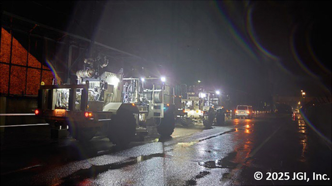
![JGI Technical Documentation [Night-time Seismic Operation]](https://jgi-inc.com/en/wp-content/themes/originaltheme/asset/img/technology/research-equipment/nocturnal-earthquake.jpg)
・S-Wave Seismic Vibrator
![JGI Technical Documentation [S-wave Vibrator]](https://jgi-inc.com/en/wp-content/themes/originaltheme/asset/img/technology/research-equipment/s-wave-vibrator.jpg)
![JGI Technical Documentation [S-wave Vibrator (Actuator)]](https://jgi-inc.com/en/wp-content/themes/originaltheme/asset/img/technology/research-equipment/actuator.jpg)
・Technical specifications of Seismic Vibrator
![JGI Technical Documentation [Technical Specifications of Vibrator Source]](https://jgi-inc.com/en/wp-content/themes/originaltheme/asset/img/technology/research-equipment/truck_01.jpg)
![JGI Technical Documentation [Technical Specifications of Vibrator Source 02]](https://jgi-inc.com/en/wp-content/themes/originaltheme/asset/img/technology/research-equipment/truck_02.jpg)
![JGI Technical Documentation [Technical Specifications of Vibrator Source 03]](https://jgi-inc.com/en/wp-content/themes/originaltheme/asset/img/technology/research-equipment/technologie-list.jpg)
▶Accelerated Impact Seismic Source (land seismic source)
This seismic source was developed by JGI and uses compressed nitrogen gas to accelerate during its fall. There are two types of sources according to target depth, JMS-65 for shallow targets and JMI-400 for deeper targets, both designed to be suitable for various survey applications.
The characteristics of the seismic source are as follows.
- ・ Capable of continuously generating pulse waves, allowing improvement of the signal to noise ratio through stacking.
- ・ Superior operational efficiency compared to other pulse sources such as hammer blows or small explosive type source(e.g., blasting-cap detonations).
- ・Capable of generating pulses for both P-waves and S-waves.
![JGI Technical Documentation [Technical Specifications of Vibrator Source 04]](https://jgi-inc.com/en/wp-content/themes/originaltheme/asset/img/technology/research-equipment/impactor-epicenter_02.jpg)
![JGI Technical Documentation [Large Impactor Source (JMI-400)]](https://jgi-inc.com/en/wp-content/themes/originaltheme/asset/img/technology/research-equipment/large-impactor-epicenter.jpg)
![JGI Technical Documentation [Small Impactor Source (JMS-65)]](https://jgi-inc.com/en/wp-content/themes/originaltheme/asset/img/technology/research-equipment/small-impactor-epicenter.jpg)
![JGI Technical Documentation [Technical Specifications of Impactor Source]](https://jgi-inc.com/en/wp-content/themes/originaltheme/asset/img/technology/research-equipment/technical-specifications.png)
▶Seismic Air Gun Source
A seismic air gun stores high-pressure air in a steel air chamber and when triggered, releases it rapidly through outlet ports into the surrounding water. The sudden release creates an air bubble that rapidly expands and subsequently collapses. The resulting oscillation of the bubble produces strong acoustic pulses that propagates through the water and into the seafloor, where part of the energy is reflected by subsurface layers. The reflected waves are recorded by hydrophones embedded in streamer cables.
The characteristics of the seismic air gun source are as follows.
- ・ Seismic pulses are continuously generated and released into the water with user-defined cycle times. (Cycle time depends on compressor capacity, air pressure, and air gun capacity.)
- ・ To improve the Primary-to-Bubble Ratio?enhancing the primary pulse wave while reducing the level of the secondary bubble wave?seismic air gun sources are generally arranged in arrays or clusters.
- ・ For single seismic air gun operations where a high PBR is required, the GI gun is commonly employed.
![JGI Technical Documentation [Panoramic View of Marine Survey Vessel]](https://jgi-inc.com/en/wp-content/themes/originaltheme/asset/img/technology/research-equipment/air-gun-epicenter-sea.jpg)
![JGI Technical Documentation [AirGun Firing Conditions]](https://jgi-inc.com/en/wp-content/themes/originaltheme/asset/img/technology/research-equipment/air-gun-epicenter-sea2.jpg)
・Principle of air gun operation
A seismic air gun generates acoustic pulses by discharging compressed air into water according to the following principle.
- A) Chambers I and II are filled with compressed air.
- B) A solenoid valve is activated to pump compressed air under the top flange of the shuttle.
- C) The shuttle is pushed up, and compressed air in chamber II is released into water.
- D) After closing the solenoid valve, the shuttle is pushed down by feeding compressed air into chamber I, and the chambers I and II are filled with compressed air.
![JGI Technical Documentation [Diagram of AirGun Operating Principle]](https://jgi-inc.com/en/wp-content/themes/originaltheme/asset/img/technology/research-equipment/elastic-wave-pulse.png)
![JGI Technical Documentation [BOLT 1900LLX, 1,520 cu-in]](https://jgi-inc.com/en/wp-content/themes/originaltheme/asset/img/technology/research-equipment/air-gun-epicenter-bolt1900.jpg)
![JGI Technical Documentation [BOLT 1500LL, 1,050 cu-in]](https://jgi-inc.com/en/wp-content/themes/originaltheme/asset/img/technology/research-equipment/air-gun-epicenter-bolt1500.jpg)
![JGI Technical Documentation [BOLT 2800LLX, 480 cu-in]](https://jgi-inc.com/en/wp-content/themes/originaltheme/asset/img/technology/research-equipment/air-gun-epicenter-bolt2800.jpg)
![JGI Technical Documentation [Deployment of Tri-Cluster AirGun]](https://jgi-inc.com/en/wp-content/themes/originaltheme/asset/img/technology/research-equipment/tri-cluster.jpg)
![JGI Technical Documentation [Deployment of Tuned Cluster AirGun]](https://jgi-inc.com/en/wp-content/themes/originaltheme/asset/img/technology/research-equipment/tuned-cluster.jpg)
![JGI Technical Documentation [AirGun Controller (Seamap GunLink2000)]](https://jgi-inc.com/en/wp-content/themes/originaltheme/asset/img/technology/research-equipment/airgun-controller.jpg)
▶Boomer Seismic Source
The boomer source was developed as a seismic source for seismic surveys in shallow coastal waters and rivers. It consists of a boomer plate?composed of a circular plate and an attached wire-wound coil?mounted on a catamaran-type float and placed several tens of centimeters below the water surface, as well as a source control unit. Upon receiving a trigger signal, the source control unit instantaneously sends a large electric current into the wire-wound coil, causing the plate to displace and generate an acoustic pulse.
The characteristics of the Boomer seismic source are as follows.
- ・ Capable of continuously generating acoustic pulses in water.
- ・ Applicable to both sub-bottom profiling (SBP) and multichannel seismic surveys.
- ・ Capable of producing high-quality impulsive seismic waveforms.
- ・ Suitable for ultra-high-resolution imaging of shallow subsurface.
- ・ Effective frequency range is approximately 300 Hz to 2,000 Hz.
- ・ Suitable for surveys in shallow coastal waters and rivers.
▶Sparkers Seismic Source
The sparker was developed as a seismic source for marine seismic surveys. It generates seismic pulse by discharging a large electric current through electrodes mounted on a steel towing frame. The system is typically towed at a depth of several tens of centimeters to a few meters below the sea surface while in use. The seismic source control device is connected to the sparker by an electric cable and supplies power necessary for discharge upon receiving a trigger signal.
The characteristics of the sparker are as follows.
- ・ Capable of continuously generating seismic pulses in water.
- ・ Usable in multichannel seismic surveys.
- ・ Energy level adjustable from several hundred joules to a maximum of 12,000 joules.
- ・ Suitable for high resolution imaging of shallow to medium subsurface layers.
- ・ Effective frequency range from several tens of Hz to approximately 1,000 Hz.
![JGI Technical Documentation [Boomer Source (AAE Technologies AA301)]](https://jgi-inc.com/en/wp-content/themes/originaltheme/asset/img/technology/research-equipment/boomer-epicenter.jpg)
![JGI Technical Documentation [Sparker Source (AAE Delta-Sparker)]](https://jgi-inc.com/en/wp-content/themes/originaltheme/asset/img/technology/research-equipment/sparker-epicenter.jpg)